


Files:
The Hello GL example demonstrates the basic use of the OpenGL-related classes provided with Qt.
Qt provides the QGLWidget class to enable OpenGL graphics to be rendered within a standard application user interface. By subclassing this class, and providing reimplementations of event handler functions, 3D scenes can be displayed on widgets that can be placed in layouts, connected to other objects using signals and slots, and manipulated like any other widget.
The GLWidget class contains some standard public definitions for the constructor, destructor, sizeHint(), and minimumSizeHint() functions:
 class GLWidget : public QGLWidget
 {
     Q_OBJECT

 public:
     GLWidget(QWidget *parent = 0);
     ~GLWidget();

     QSize minimumSizeHint() const;
     QSize sizeHint() const;
We use a destructor to ensure that any OpenGL-specific data structures are deleted when the widget is no longer needed (although in this case nothing needs cleaning up).
 public slots:
     void setXRotation(int angle);
     void setYRotation(int angle);
     void setZRotation(int angle);

 signals:
     void xRotationChanged(int angle);
     void yRotationChanged(int angle);
     void zRotationChanged(int angle);
The signals and slots are used to allow other objects to interact with the 3D scene.
 protected:
     void initializeGL();
     void paintGL();
     void resizeGL(int width, int height);
     void mousePressEvent(QMouseEvent *event);
     void mouseMoveEvent(QMouseEvent *event);
OpenGL initialization, viewport resizing, and painting are handled by reimplementing the QGLWidget::initializeGL(), QGLWidget::resizeGL(), and QGLWidget::paintGL() handler functions. To enable the user to interact directly with the scene using the mouse, we reimplement QWidget::mousePressEvent() and QWidget::mouseMoveEvent().
 private:
     QtLogo *logo;
     int xRot;
     int yRot;
     int zRot;
     QPoint lastPos;
     QColor qtGreen;
     QColor qtPurple;
 };
The rest of the class contains utility functions and variables that are used to construct and hold orientation information for the scene. The logo variable will be used to hold a pointer to the QtLogo object which contains all the geometry.
In this example, we split the class into groups of functions and describe them separately. This helps to illustrate the differences between subclasses of native widgets (such as QWidget and QFrame) and QGLWidget subclasses.
The constructor provides default rotation angles for the scene, sets the pointer to the QtLogo object to null, and sets up some colors for later use.
 GLWidget::GLWidget(QWidget *parent)
     : QGLWidget(QGLFormat(QGL::SampleBuffers), parent)
 {
     logo = 0;
     xRot = 0;
     yRot = 0;
     zRot = 0;

     qtGreen = QColor::fromCmykF(0.40, 0.0, 1.0, 0.0);
     qtPurple = QColor::fromCmykF(0.39, 0.39, 0.0, 0.0);
 }
We also implement a destructor to release OpenGL-related resources when the widget is deleted:
 GLWidget::~GLWidget()
 {
 }
In this case nothing requires cleaning up.
We provide size hint functions to ensure that the widget is shown at a reasonable size:
 QSize GLWidget::minimumSizeHint() const
 {
     return QSize(50, 50);
 }

 QSize GLWidget::sizeHint() const
 {
     return QSize(400, 400);
 }
The widget provides three slots that enable other components in the example to change the orientation of the scene:
 void GLWidget::setXRotation(int angle)
 {
     qNormalizeAngle(angle);
     if (angle != xRot) {
         xRot = angle;
         emit xRotationChanged(angle);
         updateGL();
     }
 }
In the above slot, the xRot variable is updated only if the new angle is different to the old one, the xRotationChanged() signal is emitted to allow other components to be updated, and the widget's updateGL() handler function is called.
The setYRotation() and setZRotation() slots perform the same task for rotations measured by the yRot and zRot variables.
The initializeGL() function is used to perform useful initialization tasks that are needed to render the 3D scene. These often involve defining colors and materials, enabling and disabling certain rendering flags, and setting other properties used to customize the rendering process.
 void GLWidget::initializeGL()
 {
     qglClearColor(qtPurple.dark());

     logo = new QtLogo(this, 64);
     logo->setColor(qtGreen.dark());

     glEnable(GL_DEPTH_TEST);
     glEnable(GL_CULL_FACE);
     glShadeModel(GL_SMOOTH);
     glEnable(GL_LIGHTING);
     glEnable(GL_LIGHT0);
     glEnable(GL_MULTISAMPLE);
     static GLfloat lightPosition[4] = { 0.5, 5.0, 7.0, 1.0 };
     glLightfv(GL_LIGHT0, GL_POSITION, lightPosition);
 }
In this example, we reimplement the function to set the background color, create a QtLogo object instance which will contain all the geometry to display, and set up the rendering process to use a particular shading model and rendering flags.
The resizeGL() function is used to ensure that the OpenGL implementation renders the scene onto a viewport that matches the size of the widget, using the correct transformation from 3D coordinates to 2D viewport coordinates.
The function is called whenever the widget's dimensions change, and is supplied with the new width and height. Here, we define a square viewport based on the length of the smallest side of the widget to ensure that the scene is not distorted if the widget has sides of unequal length:
 void GLWidget::resizeGL(int width, int height)
 {
     int side = qMin(width, height);
     glViewport((width - side) / 2, (height - side) / 2, side, side);

     glMatrixMode(GL_PROJECTION);
     glLoadIdentity();
 #ifdef QT_OPENGL_ES_1
     glOrthof(-0.5, +0.5, -0.5, +0.5, 4.0, 15.0);
 #else
     glOrtho(-0.5, +0.5, -0.5, +0.5, 4.0, 15.0);
 #endif
     glMatrixMode(GL_MODELVIEW);
 }
A discussion of the projection transformation used is outside the scope of this example. Please consult the OpenGL reference documentation for an explanation of projection matrices.
The paintGL() function is used to paint the contents of the scene onto the widget. For widgets that only need to be decorated with pure OpenGL content, we reimplement QGLWidget::paintGL() instead of reimplementing QWidget::paintEvent():
 void GLWidget::paintGL()
 {
     glClear(GL_COLOR_BUFFER_BIT | GL_DEPTH_BUFFER_BIT);
     glLoadIdentity();
     glTranslatef(0.0, 0.0, -10.0);
     glRotatef(xRot / 16.0, 1.0, 0.0, 0.0);
     glRotatef(yRot / 16.0, 0.0, 1.0, 0.0);
     glRotatef(zRot / 16.0, 0.0, 0.0, 1.0);
     logo->draw();
 }
In this example, we clear the widget using the background color that we defined in the initializeGL() function, set up the frame of reference for the geometry we want to display, and call the draw method of the QtLogo object to render the scene.
Just as in subclasses of native widgets, mouse events are handled by reimplementing functions such as QWidget::mousePressEvent() and QWidget::mouseMoveEvent().
The mousePressEvent() function simply records the position of the mouse when a button is initially pressed:
 void GLWidget::mousePressEvent(QMouseEvent *event)
 {
     lastPos = event->pos();
 }
The mouseMoveEvent() function uses the previous location of the mouse cursor to determine how much the object in the scene should be rotated, and in which direction:
 void GLWidget::mouseMoveEvent(QMouseEvent *event)
 {
     int dx = event->x() - lastPos.x();
     int dy = event->y() - lastPos.y();

     if (event->buttons() & Qt::LeftButton) {
         setXRotation(xRot + 8 * dy);
         setYRotation(yRot + 8 * dx);
     } else if (event->buttons() & Qt::RightButton) {
         setXRotation(xRot + 8 * dy);
         setZRotation(zRot + 8 * dx);
     }
     lastPos = event->pos();
 }
Since the user is expected to hold down the mouse button and drag the cursor to rotate the object, the cursor's position is updated every time a move event is received.
This class encapsulates the OpenGL geometry data which will be rendered in the basic 3D scene.
 class QtLogo : public QObject
 {
 public:
     QtLogo(QObject *parent, int d = 64, qreal s = 1.0);
     ~QtLogo();
     void setColor(QColor c);
     void draw() const;
 private:
     void buildGeometry(int d, qreal s);

     QList<Patch *> parts;
     Geometry *geom;
 };
The geometry is divided into a list of parts which may be rendered in different ways. The data itself is contained in a Geometry structure that includes the vertices, their lighting normals and index values which point into the vertices, grouping them into faces.
 struct Geometry
 {
     QVector<GLushort> faces;
     QVector<QVector3D> vertices;
     QVector<QVector3D> normals;
     void appendSmooth(const QVector3D &a, const QVector3D &n, int from);
     void appendFaceted(const QVector3D &a, const QVector3D &n);
     void finalize();
     void loadArrays() const;
 };
The data in the Geometry class is stored in QVector<QVector3D> members which are convenient for use with OpenGL because they expose raw contiguous floating point values via the constData() method. Methods are included for adding new vertex data, either with smooth normals, or facetted normals; and for enabling the geometry ready for rendering.
 class Patch
 {
 public:
     enum Smoothing { Faceted, Smooth };
     Patch(Geometry *);
     void setSmoothing(Smoothing s) { sm = s; }
     void translate(const QVector3D &t);
     void rotate(qreal deg, QVector3D axis);
     void draw() const;
     void addTri(const QVector3D &a, const QVector3D &b, const QVector3D &c, const QVector3D &n);
     void addQuad(const QVector3D &a, const QVector3D &b,  const QVector3D &c, const QVector3D &d);

     GLushort start;
     GLushort count;
     GLushort initv;

     GLfloat faceColor[4];
     QMatrix4x4 mat;
     Smoothing sm;
     Geometry *geom;
 };
The higher level Patch class has methods for accumulating the geometry one face at a time, and treating collections of faces or "patches" with transformations, applying different colors or smoothing. Although faces may be added as triangles or quads, at the OpenGL level all data is treated as triangles for compatibility with OpenGL/ES.
 void Patch::draw() const
 {
     glPushMatrix();
     qMultMatrix(mat);
     glMaterialfv(GL_FRONT_AND_BACK, GL_AMBIENT_AND_DIFFUSE, faceColor);

     const GLushort *indices = geom->faces.constData();
     glDrawElements(GL_TRIANGLES, count, GL_UNSIGNED_SHORT, indices + start);
     glPopMatrix();
 }
Drawing a Patch is simply acheived by applying any transformation, and material effect, then drawing the data using the index range for the patch. The model-view matrix is saved and then restored so that any transformation does not affect other parts of the scene.
 void QtLogo::buildGeometry(int divisions, qreal scale)
 {
     qreal cw = cross_width * scale;
     qreal bt = bar_thickness * scale;
     qreal ld = logo_depth * scale;
     qreal th = tee_height *scale;

     RectPrism cross(geom, cw, bt, ld);
     RectPrism stem(geom, bt, th, ld);

     QVector3D z(0.0, 0.0, 1.0);
     cross.rotate(45.0, z);
     stem.rotate(45.0, z);

     qreal stem_downshift = (th + bt) / 2.0;
     stem.translate(QVector3D(0.0, -stem_downshift, 0.0));

     RectTorus body(geom, 0.20, 0.30, 0.1, divisions);

     parts << stem.parts << cross.parts << body.parts;

     geom->finalize();
 }
The geometry is built once on construction of the QtLogo, and it is paramaterized on a number of divisions - which controls how "chunky" the curved section of the logo looks - and on a scale, so larger and smaller QtLogo objects can be created without having to use OpenGL scaling (which would force normal recalculation).
The building process is done by helper classes (read the source for full details) which only exist during the build phase, to assemble the parts of the scene.
 void QtLogo::draw() const
 {
     geom->loadArrays();

     glEnableClientState(GL_VERTEX_ARRAY);
     glEnableClientState(GL_NORMAL_ARRAY);

     for (int i = 0; i < parts.count(); ++i)
         parts[i]->draw();

     glDisableClientState(GL_VERTEX_ARRAY);
     glDisableClientState(GL_NORMAL_ARRAY);
 }
Finally the complete QtLogo scene is simply drawn by enabling the data arrays and then iterating over the parts, calling draw() on each one.
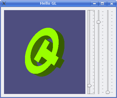
The Window class is used as a container for the GLWidget used to display the scene:
 class GLWidget;

 class Window : public QWidget
 {
     Q_OBJECT

 public:
     Window();

 protected:
     void keyPressEvent(QKeyEvent *event);

 private:
     QSlider *createSlider();

     GLWidget *glWidget;
     QSlider *xSlider;
     QSlider *ySlider;
     QSlider *zSlider;
 };
In addition, it contains sliders that are used to change the orientation of the object in the scene.
The constructor constructs an instance of the GLWidget class and some sliders to manipulate its contents.
 Window::Window()
 {
     glWidget = new GLWidget;

     xSlider = createSlider();
     ySlider = createSlider();
     zSlider = createSlider();

     connect(xSlider, SIGNAL(valueChanged(int)), glWidget, SLOT(setXRotation(int)));
     connect(glWidget, SIGNAL(xRotationChanged(int)), xSlider, SLOT(setValue(int)));
     connect(ySlider, SIGNAL(valueChanged(int)), glWidget, SLOT(setYRotation(int)));
     connect(glWidget, SIGNAL(yRotationChanged(int)), ySlider, SLOT(setValue(int)));
     connect(zSlider, SIGNAL(valueChanged(int)), glWidget, SLOT(setZRotation(int)));
     connect(glWidget, SIGNAL(zRotationChanged(int)), zSlider, SLOT(setValue(int)));
We connect the valueChanged() signal from each of the sliders to the appropriate slots in glWidget. This allows the user to change the orientation of the object by dragging the sliders.
We also connect the xRotationChanged(), yRotationChanged(), and zRotationChanged() signals from glWidget to the setValue() slots in the corresponding sliders.
     QHBoxLayout *mainLayout = new QHBoxLayout;
     mainLayout->addWidget(glWidget);
     mainLayout->addWidget(xSlider);
     mainLayout->addWidget(ySlider);
     mainLayout->addWidget(zSlider);
     setLayout(mainLayout);

     xSlider->setValue(15 * 16);
     ySlider->setValue(345 * 16);
     zSlider->setValue(0 * 16);
     setWindowTitle(tr("Hello GL"));
 }
The sliders are placed horizontally in a layout alongside the GLWidget, and initialized with suitable default values.
The createSlider() utility function constructs a QSlider, and ensures that it is set up with a suitable range, step value, tick interval, and page step value before returning it to the calling function:
 QSlider *Window::createSlider()
 {
     QSlider *slider = new QSlider(Qt::Vertical);
     slider->setRange(0, 360 * 16);
     slider->setSingleStep(16);
     slider->setPageStep(15 * 16);
     slider->setTickInterval(15 * 16);
     slider->setTickPosition(QSlider::TicksRight);
     return slider;
 }
The GLWidget class implementation shows how to subclass QGLWidget for the purposes of rendering a 3D scene using OpenGL calls. Since QGLWidget is a subclass of QWidget, subclasses of QGLWidget can be placed in layouts and provided with interactive features just like normal custom widgets.
We ensure that the widget is able to correctly render the scene using OpenGL by reimplementing the following functions:
Since QGLWidget is a subclass of QWidget, it can also be used as a normal paint device, allowing 2D graphics to be drawn with QPainter. This use of QGLWidget is discussed in the 2D Painting example.
More advanced users may want to paint over parts of a scene rendered using OpenGL. QGLWidget allows pure OpenGL rendering to be mixed with QPainter calls, but care must be taken to maintain the state of the OpenGL implementation. See the Overpainting example for more information.